This is Micro inverter or The inverter very small-sized, perform modify from the energy battery the small-sized , have the value voltage about 220V AC Volt 50HZ. By the circuit composes 2 transistors performs pulse oscillator generator or Square wave generator, for drive the coil transformer have voltage tall about 220V at 50Hz frequencies. By can change the value RC when give the frequency can modify. This circuit have current about 100mA depend on the transistor and Transformer. The detail is other total up PCB see in a picture below. Circuit Micro Inverter by 2N5121 Diagram Micro Inverter by 2N5121 Related Links Solar panel micro inverter 12Vdc to 220Vac inverter Inverter 12V to 220V 300W by NE555,2N3055 mini inverter 10W-30W by Transistor D313 Simple High Power inverter by 2N3055
↧
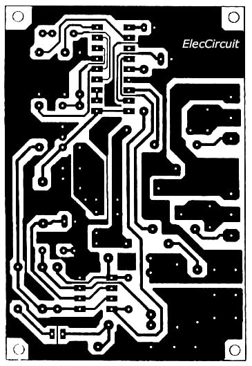
Micro Inverter by 2N6121
↧
Simple AC to DC converter 9VAC to 35VDC
Simple AC to DC converter 9VAC to 35VDC This again idea example ac to dc converter model to be simple. By modify 9VAC to 35VDC from when how many is see the circuit has already. Me uses base equipment only not? can enhance electricity pressure. See the detail in circuit picture. Related Links DC to DC converter circuit AC to DC converter circuit car dc converter DC converter step up 12V to 9V 2A step down dc converter using IC 741 and 2N3055 DC Power Supply 9 volt using TIP31 transistor DC Converter 12V to 24V 2A by IC 40106 and Mosfet BUZ11 9V to 3V Step-Down Converter by LT1073
↧
↧
12V to 220V Inverter 180W by 2N3055
This is AC Inverter circuit ,It Converts 12VDC to 220VAC Output 180W. Use easy Circuit Square Wave Oscillator Generator 50Hz. So Boost up Current High by 2N3055 Drive Transformer output 220V 50HZ From Voltage Supply 12V 10A. This circuit is converter to use to charge DC12V from the lead-acid batteries to AC 250V for use in a car, Boats or mobile homes. There are the output power There are the sufficient power to the small electronics such as a lamp or electrical soldering iron. In circuit use only six transistors, transformer and a few electronic parts. So it is easy to build and cheap, too. How it works -The Q3(BC549) and Q4(BC549) both are the a stable multivibrator (AMV) has output is pulse square wave from about 50 Hz. They will alternately inductor current. -And the power section also works on push-pull form. - When Q3 induct current will have [...]
↧
Inverter 100W 12VDC to 220V by IC 4047 – IRF540
This is inverter 100W circuit, use IC 4047 alike inverter 100W transistor I use Mosfet IRF540 instead Transistor 2N3055. It good Idae, power output 100W from transformer 2-3A. Read detail more in circuit. Related Links Power inverter 220v More circuits about IC 4047 Home power inverter More circuit about IRF540 Inverter 100W by IC 4047 + 2N3055 (with PCB) Inverter 12V to 220V 300W by NE555,2N3055 12 Volt to 220 Volt Inverter 500W Inverter 100W 12V to 220V by Transistor
↧
Mini inverter 10W-30W by Transistor D313
This is AC circuit mini inverter 10W – 30W. It Converts 12VDC to 220VAC Output 10W to 30W . Use easy Circuit Square Wave Oscillator Generator 50Hz. So Boost up Current High by D313 or H1061 or TIP41, Drive Transformer output 220V 50HZ From Voltage Supply 12V 1A – 2A. Related Links Solar panel micro inverter 12Vdc to 220Vac inverter Inverter 100W by IC 4047 + 2N3055 (with PCB) Inverter 12V to 220V 300W by NE555,2N3055 300W inverter power 24Vdc to 220Vac by MJ15003,CA3130,CD4027 Inverter 100W by IC 4047 + 2N3055 (with PCB) 12 Volt to 220 Volt Inverter 500W Inverter 100W 12V to 220V by Transistor
↧
↧
300W inverter power 24Vdc to 220Vac by MJ15003,CA3130,CD4027
This is circuit 300W Inverter power,so input battery 24V to Output 220Vac 50Hz 300W. I used main Component IC CD4027 , NE555,CA3130 and LM7805. The transistor power MJ15003,2N3773 driver transformer 24V 10A min. The VR1 – 100K is control Frequency output at 50Hz 50Hz or 60Hz at Square wave signal. The VR2 – 50K is control voltage output at 220V. Note: C6 = 0.1uf metalized-film capacitor, 5% tolerance. Please read more in image circuit. PCB:300W inverter power 24Vdc to 220Vac by MJ15003,CA3130,CD4027
↧
100W Square wave Inverter by CD4047, LM358,2SC1061,2N3055
This is AC Inverter. Input 12VDC from car battery to output 220V AC 50Hz or 60Hz at Square wave signal. The main part is IC CD4047 (or IC 4047 Series) and IC LM358 and Transistor 2SC1061 and 2N3055. The transformer is 12V-012V Primary : 220V Secondary. and current 3A up for power output than 100W. Note: C1 = 0.1uf metalized-film capacitor, 5% tolerance. R1 = 47K for 50Hz output, 39K for 60Hz output. Related Links More circuit about 2N3055 More circuit about C1061 More Circuit about IC LM358 All Circuits use IC 4047 Power inverter 220v Inverter 100W 12V to 220V by Transistor
↧
DC to AC Inverter by IC 555 and TIP41 TIP42
This be basic AC inverter Circuit. Convenient for the initiator who have to is extremely fond of something experience. Because of use IC 555 highly popular, perform produce the frequency ,then enlarge with transistor NPN and PNP number TIP41 and TIP42 drive the coil transformer. Get by can pay Voltage output about 120V to 230V at frequency 50Hz. By have R4 perform control the frequency and should use. Voltage supply about 5V to 15V the detail sees in circuit picture sir. Related Links 12Vdc to 120Vac inverter Solar panel micro inverter IC-555 circuits Inverter 100W 12V to 220V by Transistor
↧
SCR Mini Power Inverter
This be Mini Power Inverter , by use SCR be main part electronics , perform Oscillator Generator 400Hz give Output 300V by use Voltage Input 12V Current 0.8A. The only drawback with this circuit is that it might latch in the conducting state if the load is too heavy or if there is a short at the output, this requires some kind of protection, on the input line, in the form of a fuse or similar. The transformer used is a 10W mains type with 6V+6V windings on the SCR side and a 110V+110V windings, in series, at the output. Efficiency is 50% and the ideal load is equivalent to a 22k resistor, 5W. The output waveform is vaguely sinusoidal at a frequency of 400Hz. In addition to this circuit. You can see the other circuits. Having similar properties such as: Micro Inverter by 2N6121 This is Micro inverter or [...]
↧
↧
Transistor inverter circuit
See your inverter circuit. The operation of the circuit can learn simple and easy to buy the equipment. I recommend using transistor circuits. This circuit has several very Here are three examples below. Inverter 12V to 220V 100W by Transistor This circuit power Inverter 100W, it easy and good ideas. When use the electric appliances that want 220V AC 50HZ, which have small-sized … Mini inverter 10W-30W by Transistor D313 This is AC circuit mini inverter 10W – 30W. It Converts 12VDC to 220VAC Output 10W to 30W. Use easy Circuit Square Wave Oscillator … 100w transistor inverter circuit diagram This is transistor inverter circuit diagram 100watt it sizes are easy circuit. Because of use the all transistor, have no the integrated … Mini Inverter 12V to 120V by TIP32 Ever needed a low power 120volt AC power source for your car, van or truck? Well this circuit should do [...]
↧
Simple working principle of the inverters
 The inverter working principle as shown in Figure 1. The main device is a transformer. Which have 12V-0-12V, a common iron core. But instead we use the power input as 220 volts. Then power output as 12 volts. The way the switch differential is power AC input as 12 volts and output to AC 220 volts. The 12 volts input power source is a battery Be Supply into the center tap of the coil 12 volts. Which is now considered a power pack or coil primary. The ends of the wire on both sides (points A and B) And it will be connected via a 2-way switch to ground. Which if the switch connected at A point, will cause an electric current number one, flows from the positive terminal of the battery, into the center tab point. Then flows up to the top, through the contacts A of the switch [...]
↧
Operation of 200 watt inverter diagram
 Yesterday, I recommend Simple working principle of the inverters. Which you have understood well. Today we see Operation of 200 watt inverter diagram continuously. In the block diagram of Figure 1. Starting from the frequency generator circuit or the oscillators that works with IC2 numbers SG3526 Which is IC pulse width modulation as figure 2 shows the internal structure. Served to genered the rectangular signal on frequency 50Hz output to Output A and B. Which both these output signals have phase difference of 180 degrees all the time. That is if a Status Output A High, Output B will be low. Or If Output A is Low, Output B will be the High instead. These two signals are sent to control the output transistors Q1 and Q2. Figure 1 is 200watt inverters block diagram Both transistors Q1 and Q2 are Enhancement MOSFET type of N channel So not conduct current [...]
↧
An oscillator of the 200 watts power inverter
 From the article “Operation of 200 watt inverter diagram” and “Simple working principle of the inverters” You can understand reasonably the basis of this project. Friends would like to know that how this circuit works. Because the content very reasonably. I would like to divide the sectional. You will never be bored. Scroll to read more content and the site loads slow. We see circuit real use. As shown below. Which has working principle of the circuit is divided into three sections are a oscillator, output and protection section. But today I’m talking the oscillator circuit before. Starting when push switch-S1 which is switch turn on voltage +12V will be send to diode-D3 provided the IC2-SG3526N at pin 14. To pass through resistor-R12 of 33 ohm, there are C1 as decoupling backup current to IC2-SG3526N. The bring a positive voltage. Which is the supply voltage IC2-SG3526N to via the diode-D3 [...]
↧
↧
The output circuit of 200 watts home power inverter.
 A previous article(An oscillator of the 200 watts power inverter) I say about the frequency generator circuit of the our 200 watts home inverter. The next we see part of output as well. As show figure below When IC2-SG3526 can generate the square wave frequency of 50Hz output at pin 13 and pin 16. Both signal that has Phase difference is 180 degrees will send to R13 and R15, to bias pin gate of both transistors Q1 and Q2 number IRFP054. Which are mosfet type N channel, that has diode damper Diode is within, makes both of transistors alternately conduct current. If any one has a bias. signal at gate pin as high will can conduct current(ON). But if it get signal as low will stop conduct current(OFF). The conduct currents of the two transistors. Cause current to flow in primary coil of transformer T1 into drain out to the [...]
↧
200 watts home power inverter project using SG3526N
 I’m been talking about the the 200 watts home power inverter projects many articles. Include the following article. 1. Simple working principle of the inverters 2. Operation of 200 watt inverter diagram 3. An oscillator of the 200 watts power inverter 4.The output circuit of 200 watts home power inverter. 5. How to build the [...]
↧
How to build the 200 watts home inverter projects
 You read the article about 200 watts home inverter projects If you are interested in creating this project.Let’s see how to do. Starting from to make PCB as shown in Figure 1. and Check for any error of the copper. Especially between pin of IC2-SG3526N. Which is small, easily fail and short circuit Should be [...]
↧
High Voltage mini power supply by 2N2222
This be Mini high voltage generator at my friend wants. Because of use the transistor 2 pcs only just,build small-sized easy good. By this circuit gives pulse Generator 220V from 9V batteries and Give pulse voltage tall arrive at 170V from the 1 dry piece cell(Batt 1.5V) we should do circuit this experiment with neon [...]
↧
↧
High volt shock by transistor 2SC458
This the high voltage circuit pressure from the low beam in the character High volt shock. When switch S1 close the circuit for feed power supply give with Q1 and Q2. By current flow through coil of transformer of the primary and touch limit current with R1 and R2 already change come in pin way [...]
↧
Small AC inverter circuit using CD4047
This is a small AC inverter. There are very small amounts. For the experimental study. Because low power of around less than a 60 watt only. However, you still can get a good basic circuit course. This circuit we use an IC-4047 as astable/monostable multivibrator that low power is main of circuit In the operation [...]
↧
30W-simple inverter using 6 transistors.
This is small inverter on 30 watts, It converts DC voltage from 12V battery to AC 220V-230V at 50Hz which is electricity same use in your house. It can provide 2-3 Air pump or other. You will like them because so cheap and easy to builds. The Air Pump requirement Before see the Aquarium Air […]
↧